EDC Building | Occupancy | Demand-controlled ventilation
Criticality Ratio
Override:
Demand-controlled ventilation
Demand-controlled ventilation (DCV) is a ventilation control strategy that ensures ventilation is provided when and where it is needed, and in the amount that it is needed, to improve both energy use and comfort in the building. This is achieved by monitoring CO2 concentrations and motion detector activity in zones and increasing or decreasing the
minimum zone primary airflow as needed. The zone primary airflow is still allowed to increase above the minimum level when space conditioning loads (i.e., heating and cooling demand) dictate. Simultaneously, the outdoor air ratio (OAR), or the amount of outdoor (i.e., fresh) air in the supply air can be increased or decreased depending on the total ventilation
demands of the zones (referred to as the Ventilation Rate Procedure (VRP) in ASHRAE Standard 62.1). This style of DCV - where the zone minimum primary airflows and OAR are dynamically balanced - is referred to as ASHRAE RP-1747 CO2-based DCV.
The criticality ratio represents how much outdoor (i.e., fresh) air is entering a zone, relative to the minimum ventilation requirements and the maximum amount of outdoor air that the variable air volume (VAV) terminal unit can provide at the current system-level outdoor air ratio (OAR). Unoccupied spaces have a criticality ratio of zero as no ventilation
is required. A criticality ratio of one means that the VAV is provided the maximum amount of outdoor air possible at the current OAR but is still unable to satisfy the minimum ventilation requirement. As the criticality ratio of a zone begins to approach one (i.e., as occupants enter the space and/or CO2 concentration increase), more and more airflow will
be 'requested' from the VAV. The number of requests determines how much the minimum zone primary airflow setpoint will 'trim' or 'respond'. Ideally, the criticality ratio of a zone should hover between 0.7 and 0.8, corresponding to as low a zone primary airflow as possible while leaving some room for response.
The minimum zone primary airflow setpoint is calculated for each zone and is based on the sensors available, expected occupancy and occupancy category, geometry of each zone, and the zone air distribution effectiveness. This represents the lowest possible volume of supply air that can enter the zone for ventilation purposes. The variable air volume
(VAV) terminal unit uses trim and respond (T&R) logic to 'trim' or decrease the zone primary airflow incrementally down to the minimum setpoint if the conditioning load is satisfied and if the occupancy and/or CO2 concentrations in the zone have decreased. If no occupants are detected in the space, the ventilation can be turned off completely until
either an occupant arrives, or space conditioning is required. Similarly, if the current zone primary airflow is below the minimum setpoint due to an increase in occupancy and/or CO2 concentration in the zone, the VAV terminal unit can 'respond' or increase the zone primary airflow incrementally up to the minimum setpoint. This process is repeated
every 10-minutes in each zone. The amount that a VAV terminal unit 'trims' or 'responds' is determined by the criticality ratio of the zone.
The following calculations are performed dynamically in each zone at 10-minute timesteps.
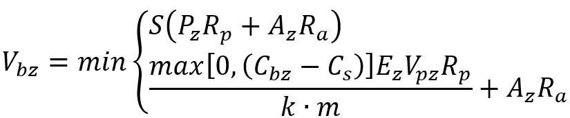
First, the breathing zone outdoor airflow rate (Vbz) is calculated. The calculation for zones with motion detectors and CO2 sensors is described by Equation A. S is the binary zone occupied status based on the motion detector (i.e., 0 is unoccupied, 1 is occupied); Pz and Az are the zone population (persons) and area (m2),
respectively; Rp and Ra are the people and area outdoor air rates (L/s), respectively, per Table 6-1 of ASHRAE Standard 62.1-2022; Cbz and Cs are the breathing zone CO2 concentrations and supply air CO2 concentrations at the air handler (ppm), respectively; k is the CO2 generation rate (assumed to be 0.00383 L/s/met/person); and m is the
typical metabolic rate of the occupants (assumed to be 1.2 met).
Equation A
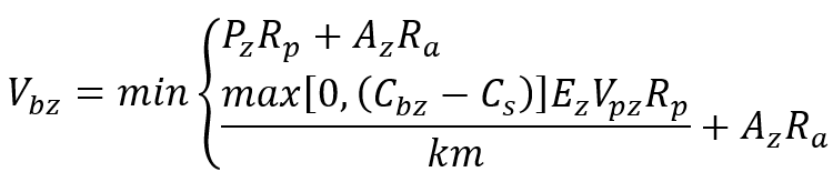
The calculation for zones with CO2 sensors only is described by Equation B. This equation differs from Equation A only in that the binary zone occupied status S is omitted, and therefore ventilation is provided on a per person and area basis as occupancy status is not known due to the lack of a motion detector.
Equation B
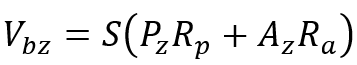
The calculation for zones with motion detectors only is described in Equation C. Since CO2 data is not available, the only information that can be used to calculate Vbz is based on the values provided in Table 6-1 of ASHRAE Standard 62.1-2022. Similar to Equation A, ventilation can be reduced to zero during occupied-standby mode due to the binary occupancy data provided by the motion detector.
Equation C
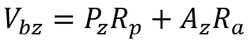
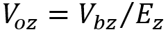
Finally, all other zones (i.e., zones with no motion detection or CO2 sensors) use the default Vbz described in by ASHRAE Standard 62.1-2022, defined by Equation D. After the Vbz is calculated for each zone, the zone outdoor airflow (Voz) is determined by Equation E. Ez corresponds to the zone air distribution effectiveness as described in
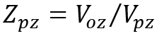
Table 6-4 of ASHRAE Standard 62.1-2022. The Ez for the low-velocity wall-mounted displacement ventilation system used in this building is typically 1.2. The zone primary outdoor air fraction (Zpz) can be calculated using Voz and the zone primary airflow rate (Vpz) as determined in Equation F.
Equation D
Equation E
Equation F
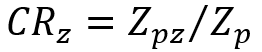
The criticality ratio (CRz) can finally be determined by dividing the Zpz by the maximum zone primary outdoor air fraction (Zp). This ratio essentially represents how much outdoor air is entering the zone relative to how much outdoor air could be provided if the variable air volume (VAV) terminal unit's zone primary airflow was maximized.
Equation G
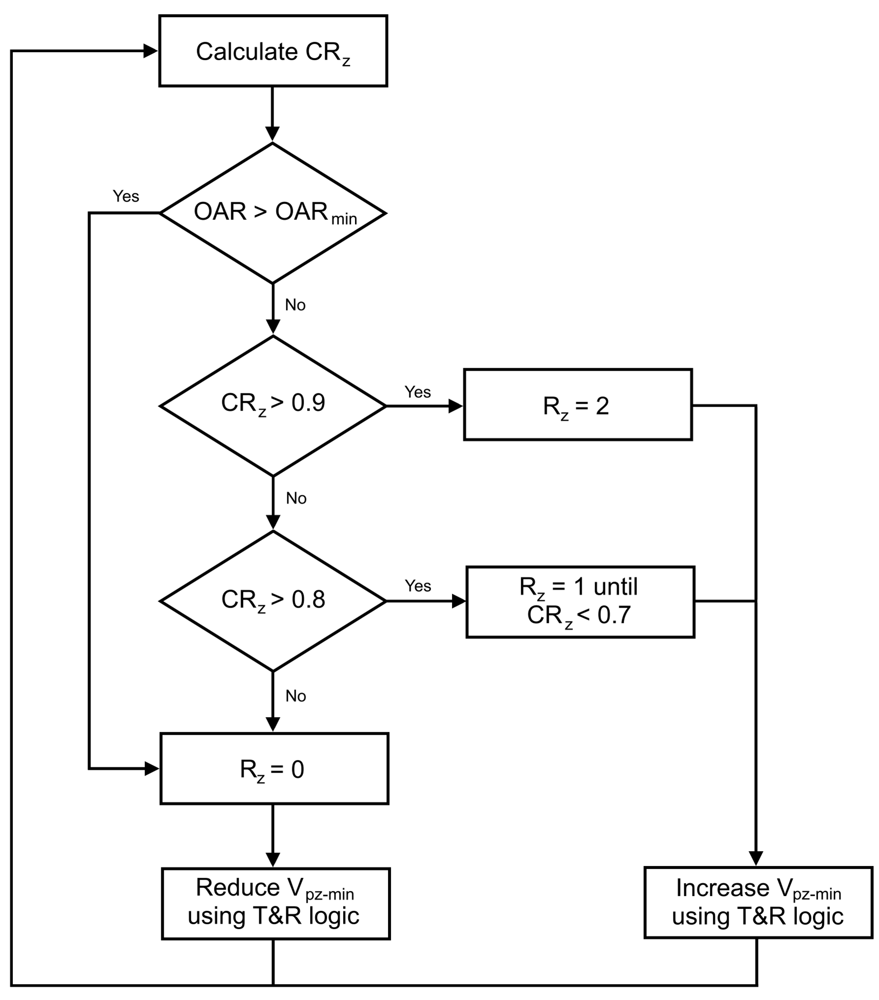
Once the CRz is determined, the control logic depicted in Figure 1 determines the number of requests (Rz) for additional air that will be sent to the VAV controller, based on the outdoor air ratio (OAR) (i.e., if the unit is economizing or not).
If the unit is economizing or the zones are not above a CRz of 0.8, then the minimum zone primary airflow setpoint (V(pz-min))
will be incrementally reduced. This reduces the total volume of air moving through the system since the OAR in the system primary airflow (Vps) is high, thus reducing fan energy use.
If the unit is not economizing (i.e., at minimum OAR during mechanical heating and cooling), then V(pz-min) will be incrementally increased. This increases the total volume of air moving through the system since
the OAR in the Vps is low, reducing heating and cooling coil energy use at a small cost to zone terminal heating devices.
Figure 1: Control logic
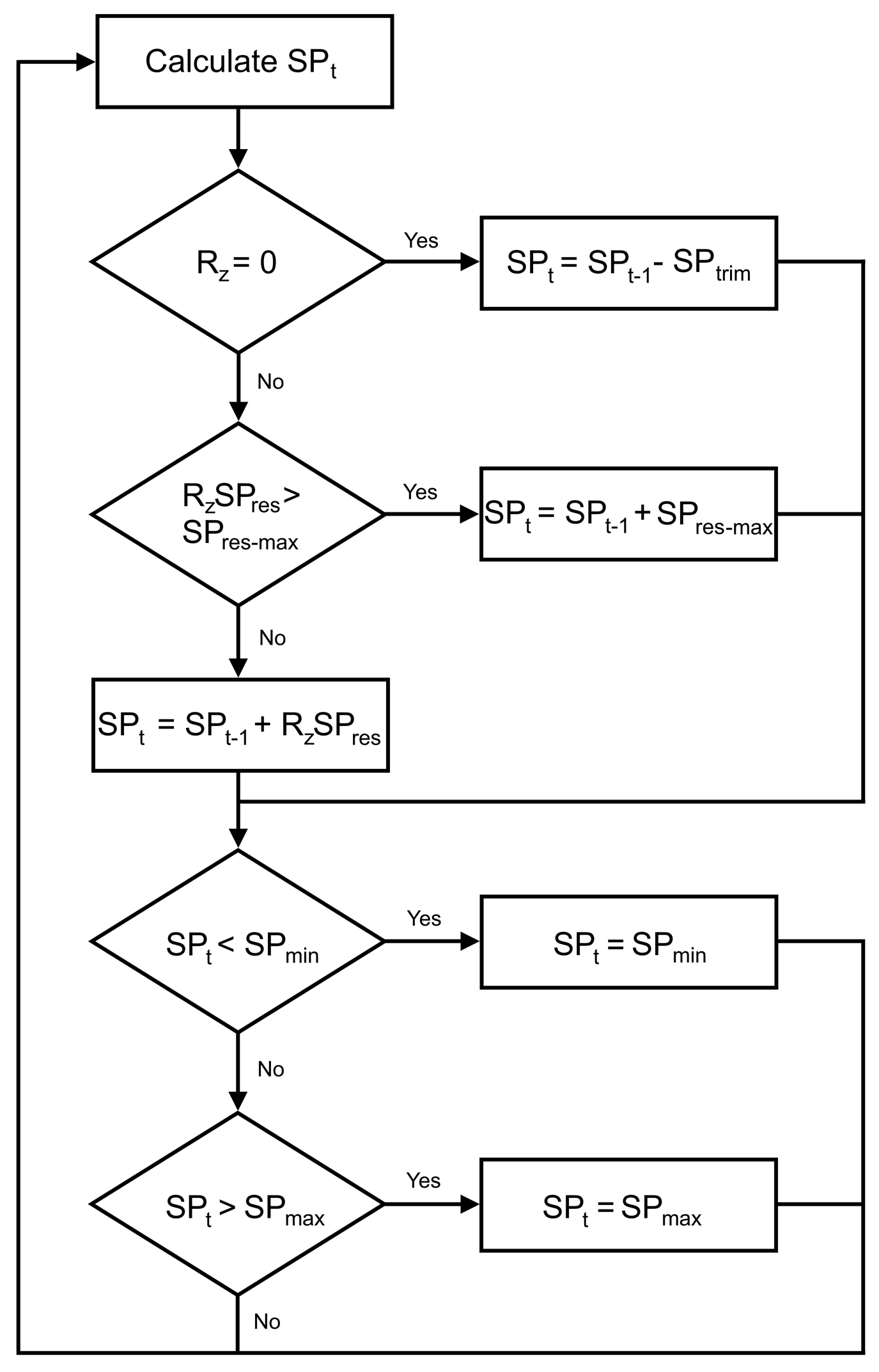
Figure 2: Trim-and-respond logic
Subsequently, the trim and respond (T&R) logic is used to reduce the V(pz-min) depending on the Rz determined in Figure 1, see Figure 2. Note that SPt represents the setpoint of interest (i.e., in this case, V(pz-min)) at time t, which is based on an increase or decrease to the setpoint from the previous timestep (SP(t-1)) by an amount RzSPres
or SPtrim, respectively. RzSPres is limited to a maximum change at each timestep (SP(res-max)) to promote control stability and ensure gradual ramping of airflow.
The setpoint is also subject to the upper and lower Vpz of the VAV (i.e., typically from no flow when unoccupied up to the maximum design capacity of the VAV).
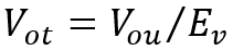
At the air handling unit (AHU) level, the OAR is determined based on ASHRAE Standard 62.1-2022 Ventilation Rate Procedure (VRP). The total uncorrected outdoor air intake (Vou) is calculated as the sum of the Vbz requirements for each zone since occupant diversity (D) is assumed to be approximately one in the building, resulting in a system ventilation efficiency (Ev) of 0.75. The outdoor air intake (Vot) is then calculated using Equation H.
Equation H
The DCV module is then able to communicate with the Mixing Box Damper module to monitor and utilize the relationship between the outdoor air damper (OAD) position and OAR to determine the new appropriate minimum OAD position for ventilation purposes, since their relationship is empirically derived and non-linear in nature. The new V(pz-min) and OADmin are then pushed to the building automation system (BAS) for control purposes.